


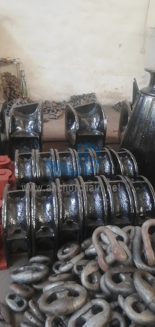
ISO 13713 Mooring And Towing Fittings Mooring Chocks Chock:steel casting material having a yield point of not less than 235 N/mm2 or equivalent. The chock contents of the steel casting are not to be more than 0.23% considering weldability.
Chock:steel
casting material having a yield point of not less than 235 N/mm2 or equivalent.
The chock contents of the steel casting are not to be more than 0.23%
considering weldability.
All
surface of the mooring chocks,including welding,shall be free from any visible flaws or imperfections.
All surfaces in contact with the ropes shall be free from surface roughness or
irregularities likely to cause damage to ropes by abrasion
The mooring chocks shall be coated externally with an anti-corrosion protective
finish.
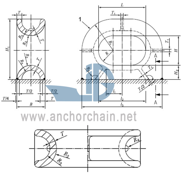
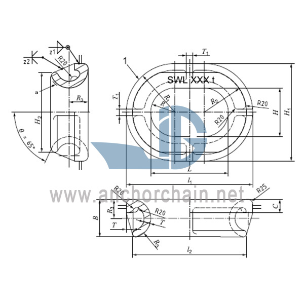
Type
A :Deck-mounted mooring chock
Type B:Bulwark-mounted mooring chock
|
Nominal size L*H |
l1 |
l2 |
l3 |
B |
H1 |
H2 |
R |
R1 |
R2 |
|
250*200 |
100 |
250 |
444 |
160 |
377 |
80 |
100 |
197 |
80 |
|
300*250 |
110 |
300 |
536 |
200 |
468 |
100 |
125 |
243 |
100 |
|
350*250 |
125 |
350 |
608 |
220 |
489 |
110 |
125 |
254 |
110 |
|
400*250 |
135 |
400 |
682 |
240 |
511 |
120 |
125 |
266 |
120 |
|
450*250 |
150 |
450 |
760 |
260 |
535 |
130 |
125 |
280 |
130 |
|
500*250A |
175 |
500 |
832 |
280 |
556 |
140 |
125 |
291 |
140 |
|
500*250B |
175 |
500 |
840 |
280 |
560 |
140 |
125 |
295 |
140 |
|
Nominal size L*H |
R3 |
R4 |
R5 |
T |
T1 |
Welding leg lengtha |
SWLb |
Calculated Weightc (kg) |
|
|
Z1 |
(KN) |
(t) |
|||||||
|
250*200 |
46 |
20 |
15 |
34 |
18 |
8.5 |
353 |
36 |
73 |
|
300*250 |
64 |
25 |
20 |
36 |
20 |
9 |
491 |
50 |
121 |
|
350*250 |
72 |
30 |
20 |
38 |
20 |
9.5 |
589 |
60 |
151 |
|
400*250 |
78 |
30 |
20 |
42 |
23 |
10.5 |
736 |
75 |
200 |
|
450*250 |
80 |
30 |
20 |
50 |
28 |
12.5 |
981 |
100 |
280 |
|
500*250A |
88 |
30 |
20 |
52 |
30 |
13 |
1128 |
115 |
338 |
|
500*250B |
80 |
30 |
20 |
60 |
36 |
15 |
1373 |
140 |
396 |
|
a The welding method may be changed based on the same welding volume/strength. b The SWLs shown are for reference only. These are based on the loadings as mentioned in Annex A. The “SWL” may be adjusted depending on the actual loading conditions,and the actual marking shall be agreed between the user and the manufacturer. c The calculated weight is for reference only. |
|||||||||
|
Nominal size L*H |
l1 |
l2 |
B |
H1 |
H2 |
C |
R |
R1 |
R2 |
|
250*200 |
450 |
398 |
154 |
408 |
327 |
57 |
100 |
200 |
174 |
|
300*250 |
516 |
460 |
168 |
466 |
387 |
60 |
125 |
233 |
205 |
|
350*250 |
582 |
520 |
177 |
482 |
395 |
65 |
125 |
241 |
210 |
|
400*250 |
652 |
588 |
193 |
502 |
412 |
70 |
125 |
251 |
219 |
|
450*250 |
734 |
662 |
213 |
534 |
433 |
77 |
125 |
267 |
231 |
|
500*250A |
812 |
730 |
237 |
562 |
447 |
82 |
125 |
281 |
240 |
|
500*250B |
828 |
750 |
253 |
578 |
466 |
82 |
125 |
289 |
250 |
|
Nominal size L*H |
R3 |
T |
T1 |
Welding leg lengtha |
SWLb |
Calculated weightc (kg) |
|||
|
Z1 |
Z2 |
(KN) |
(t) |
||||||
|
250*200 |
78 |
26 |
20 |
8 |
8 |
353 |
36 |
48 |
|
|
300*250 |
85 |
27 |
24 |
8 |
9.5 |
491 |
50 |
83 |
|
|
350*250 |
90 |
29 |
25 |
9 |
10 |
589 |
60 |
100 |
|
|
400*250 |
98 |
34 |
32 |
9.5 |
13 |
736 |
75 |
145 |
|
|
450*250 |
108 |
41 |
36 |
12.5 |
14.5 |
981 |
100 |
215 |
|
|
500*250A |
120 |
41 |
36 |
12.5 |
14.5 |
1128 |
115 |
235 |
|
|
500*250B |
128 |
48 |
41 |
14.5 |
16.5 |
1373 |
140 |
266 |
|
|
a The welding method may be changed based on the same welding volume/strength b The SWLs shown are for reference only. These are based on the loading as mentioned in Annex A c The calculated weight is for reference only. |
|||||||||


